The Mission
Radar and electronic warfare test benches have to recreate the real world before a system ever sees it. That means hopping across bands in microseconds, layering pulsed and chirped emitters, and keeping several channels locked in phase so an angle-of-arrival or multi-emitter scene holds together. Whether the work is threat emulation, receiver stress testing, or jammer development, the signal source sets the ceiling on how realistic the scene can be.
The Challenge
A static CW tone tells you almost nothing about how a modern radar or EW receiver behaves. Engineers need agile frequency switching to walk a frequency-hopping emitter, pulse modulation with clean rise and fall, and wideband chirps for LFM radar. Dense environments add another demand: multiple coherent channels that can play different emitters at once without drifting apart. The faster the switching and the tighter the phase relationship, the closer the bench gets to the field.
Recommended Berkeley Nucleonics Solutions
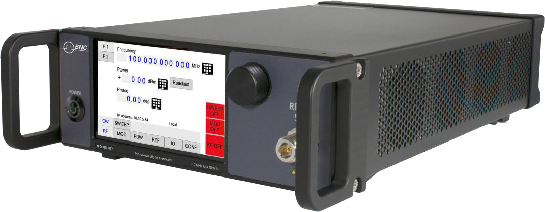
The Model 875 is the vector flagship for this work. It carries internal I/Q modulation, pulse descriptor word (PDW) playback, real-time PDW streaming over its Fast Control Port, and 200 ns vector switching, which lets it stand in for sophisticated agile emitters. Available to 40 GHz with 1, 2, 3, or 4 phase-coherent channels, it builds layered, realistic threat scenes.
When the priority is raw switching agility across many channels, the Model 825-M reaches 5 us switching with Option FS and offers up to four phase-coherent outputs in 1U, with chirp and pulse modulation built in. For the widest coverage, the Model 870A spans 100 kHz to 54 GHz with up to four channels and is documented for PDW workflows. The Model 855B adds the family's highest output power (+25 dBm) across up to eight phase-coherent channels, useful for driving long cable runs and multi-emitter angle scenes. For phase-coherent coverage past 50 GHz, the Model 871 reaches 51 GHz with 5 us switching (Option FS).
Why It Works
These sources share a phase-coherent architecture, so adding channels does not mean giving up the timing relationships an EW scene depends on. Fast-switching options let a single instrument emulate frequency-agile emitters rather than a fixed tone. Pulse and chirp modulation are native, not bolted on, and the 875's PDW playback turns a recorded or synthesized threat list into a played-back RF environment. The result is a bench that exercises a receiver the way an operational environment will.
Getting Started
Berkeley Nucleonics applications engineers help match the right source, channel count, and options to your test plan. Tell us your frequency span, switching budget, and channel needs, and we will recommend a configuration and arrange a demo.
Contact info@berkeleynucleonics.com or call 800-234-7858. Browse the full family on the RF & Microwave Signal Generators documentation page.