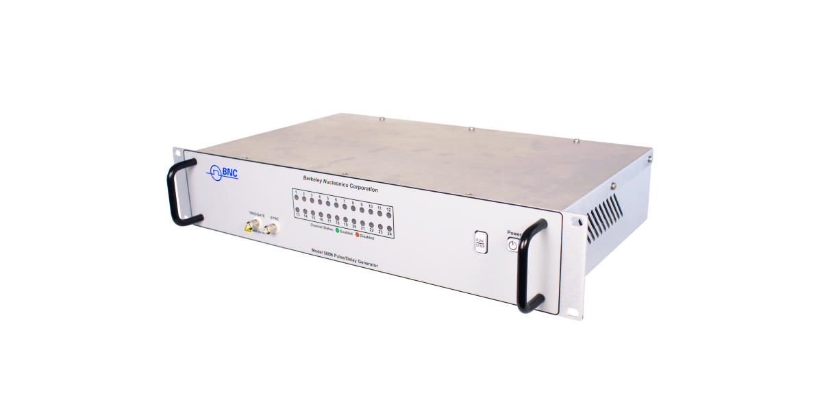
Model 588B 12 or 24-Channel Rackmount Pulse Generator
A rackmount pulse generator built for high channel density. Twelve channels in a 1U chassis or twenty-four in a 2U chassis, with up to thirty-six independent outputs, 250 ps delay resolution, and ultra-low jitter below 5 ps RMS for precision multi-channel synchronization.
Berkeley Nucleonics Corporation
1Overview
Verification notes. Values are drawn verbatim from the Model 588B datasheet (V1.1, dc-11605202). Confirm against the current released datasheet before quoting. Output-module figures depend on the modules ordered.
The Model 588B Pulse Generator has a powerful set of functions that serve various modes of operations and applications. Both the system timer and the channel timer combine to provide the ability to generate complex waveforms. BNC offers the 1U unit for 12 channels or the 2U unit for 24 channels.
These units provide precision timing and synchronization to effectively trigger any series of events or necessary equipment with up to 36 independent outputs, dual inputs with gate/trigger or optional dual trigger, and an external clock reference input. Delay resolution is 250 ps, delay accuracy is 1 ns plus 0.0001 times the period, and channel-to-channel jitter stays below 5 ps RMS.
2Key Features
250 ps delay resolution
< 5 ps RMS jitter
1 ns + .0001 x period delay accuracy
USB / RS232 / Ethernet communications
Twelve channels (1U) or twenty-four channels (2U), up to thirty-six independent outputs
System timer plus per-channel timers for complex waveforms
Dual inputs with gate/trigger or optional dual trigger
External clock reference input
3Channels & Timing Architecture
The 588B is built around a system timer with independent per-channel timers. Each channel sets its own delay and width, so a single instrument can drive a dozen or two dozen precisely timed edges across one experiment. The case for high density is straightforward: where a four-channel or eight-channel instrument would need three units to reach twenty-four edges, the 588B does it in one 2U chassis, and every channel shares the same low-jitter time base.
Delay covers 0 to 2,000 s and width covers 10 ns to 2,000 s, both at 250 ps resolution. An external clock reference input lets the instrument lock to a system clock, keeping all channels coherent with the rest of the setup. The ultra-low jitter below 5 ps RMS is what makes the high channel count usable for precision synchronization rather than just count.
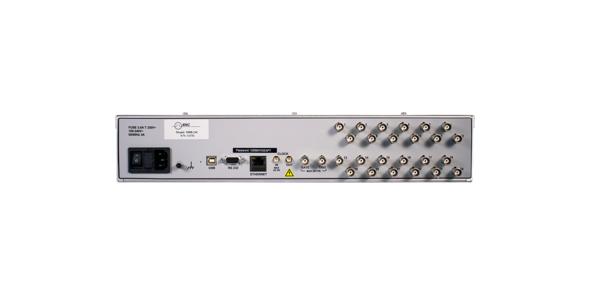
Rear panel. High-density channel outputs, trigger and gate inputs, and clock reference.
4Specifications
Internal Rate Generator
Parameter
Value
Rate (T0 period)
50 ns to 5,000 s (0.0002 Hz to 20.000 MHz)
Resolution
5 ns
Accuracy
1 ns + .0001 x period
Jitter
< 5 ps RMS
Settling
1 period
Burst Mode Counter
1 to 4,000,000,000 pulses
Duty Cycle Mode Counters
1 to 4,000,000,000 pulses
Cycle Counter
1 to 10,000,000 cycles
Timebase
200 MHz, low jitter PLL
Oscillator
50 MHz, 25 ppm
System Output Modes
Single pulse, burst, duty cycle, external gate/trigger
Pulse Contol Modes
Internal rate generator, external trigger/gate
Channel Timing Generator
Parameter
Value
Channel Output Modes
Single shot, burst, duty cycle, normal
Control Modes
Internally triggered, externally triggered and external gate. Each channel may be independently set to any of the modes.
Burst Mode Counter
1 to 10,000,000 pulses
Duty Cycle Mode Counters
1 to 10,000,000 pulses
Wait Function Counter
0 to 10,000,000 pulses
Output Multiplexer
Up to five (5) channel timers may be routed to each output channel.
Timebase
Same as internal rate generator
Delays
Parameter
Value
Delay Range
0 - 2,000 s
Width Range
10 ns - 2,000 s
Accuracy
1 ns + 0.0001 x Delay
Resolution
250 ps
Pulse Inhibit Delay
< 120 ns typical
Output Inhibit Delay
< 50 ns typical
5Output Module Specifications
The standard output is the TTL/Adjustable Dual Channel Output Module, with an output impedance of 50 ohm. It operates in either a fixed TTL/CMOS mode or an adjustable mode.
TTL/CMOS Mode
Parameter
Value
Output Level
4.0 V typ into 1 kohm
Rise Time
3 ns typ (10% - 90%)
Slew Rate
> 0.5 V/ns
Jitter
50 ps RMS channel to channel
Adjustable Mode
Parameter
Value
Output Level
2.0 to 20 VDC into 1 k ohm; 1.0 to 10.0 VDC into 50 ohm
Output Resolution
10 mV
Current
200 mA typical, 400 mA (short pulses)
Rise Time
15 ns typ @ 20 V (high imp); 25 ns typ @ 10 V (50 ohms) (10% - 90%)
Slew Rate
> 0.1 V/ns
Overshoot
< 100 mV + 10% of pulse amplitude
6Triggering & Inputs
System External Trigger/Gate Input(s)
Trigger Input
Parameter
Value
Type
Pulse 0.5 to 30v, switch closure (footswitch, safety interlock, etc.)
Function
Generate individual pulses, start a burst or continuous
Rate
DC to 1/ (200 ns + longest active pulse). Maximum of 5 MHz
Slope
Rising or Falling
Gate Input
Parameter
Value
Mode
Pulse inhibit or output inhibit
Polarity
Active high/active low
Channel Behavior
Global w/Individual Channel Control
Trigger/Gate Dual Input Module (Standard)
Standard dual channel input module, providing one trigger input, one gate input and one dual purpose input on the front panel.
The full options and ordering chart is not published on the product page and should be confirmed with Berkeley Nucleonics when configuring a unit (verify).
9Applications
ICCD and PIV testing
Laser triggering and gating
Pulsing devices under test and pump lasers
Radar and sonar simulation
High-speed photography
10Ordering / In the Box
Specify channel count (twelve or twenty-four), output-module type, and input options when ordering. The instrument ships as a 19-inch rackmount unit with power cord and a calibration certificate.